So building on the thermometer, i want it to be displayed on a 4 digit 7 segment display... i want to use a shift register to control the LEDs.. but first im going to have to learn what they are and how to use them.
74HC595 Shift Register
"8-bit serial-in, serial or parallel-out shift register with output latches; 3-state."
So this shift register is 8 bit, it can access 8 bits of information in a single machine instruction. Because each bit has two possible states "on" and "off" and there are 8 bits, this gives 256 possible combinations... e.g. 2*2*2*2*2*2*2*2 = 2^8
Serial output
Uses "synchronous serial communication" which means we can pulse one pin on and off communicating a data byte, bit by bit, the bits are separated by pulsing the clock pin.
Parallel output
"asynchronous communication" uses the Serial.begin() function of arduino, the data rate must be set on the sender and receiver. When the whole byte (8bits) are received the register deals them out to each output pin, then they are executed at the same time.Connecting another
There is an option to use the serial out pin the transmit the serial information out to another register unchanged. Meaning you can transmit 16 bits of information where the first 8 will be passed though the first chip and expressed in the second.3 states
Means HIGH, LOW and high impedance. This means the entire chip is set to low current, high voltage. Its uses include an LED array that might need to be controlled by different micro controllers depending upon its setting.
The Pin-Outputs are.....
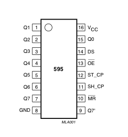 | PINS 1-7, 15 | Q0 " Q7 | Output Pins |
| PIN 8 | GND | Ground, Vss | |
| PIN 9 | Q7" | Serial Out | |
| PIN 10 | MR | Master Reclear, active low | |
| PIN 11 | SH_CP | Shift register clock pin | |
| PIN 12 | ST_CP | Storage register clock pin (latch pin) | |
| PIN 13 | OE | Output enable, active low | |
| PIN 14 | DS | Serial data input | |
| PIN 16 | Vcc | Positive supply voltage |
What happens inside the chip?
When the clockPin (SH_CP) switches from LOW to HIGH the shift register reads the state of the dataPin (DS). When the shift register is full the latch is switched to HIGH this sends the information to the storage register then to the outputPins.. The rabbit hole gets deeper...

Creating a circuit

Turning it on
GND (pin 8) to ground
Vcc (pin 16) to 5V
OE (pin 13) to ground
MR (pin 10) to 5V
Connect to Arduino
DS (dataPin) (pin14) to Arduino DigitalPin 11
SH_CP (clockPin) (pin 11) to Ardunio DigitalPin 12
ST_CP (latchPin) (pin 12) to Arduino DigitalPin 8
So whats next..?
Well the code in example two looks interesting i can type a number into the serial and the corresponding LED will illuminate( Pin 15 is 1). I can see how the hardware side works, now ive got to work on the programming..
Phillip`s data sheet for 74HC595
No comments:
Post a Comment